DCS004
SECRET FIX CLADDING
DCS004 SYSTEM OVERVIEW
Downer DCS004 Framing System is designed to provide a mechanical secret fix support to most rainscreen cladding panels using the principle of a ventilated façade.
DCS004 MSF can be installed onto our DCS031 HELPING HAND®, DCS041 Floor to Floor or DCS021 Omega & Zed system offering design freedom to suit project specific thermal and structural demands and variation in cavity depths.
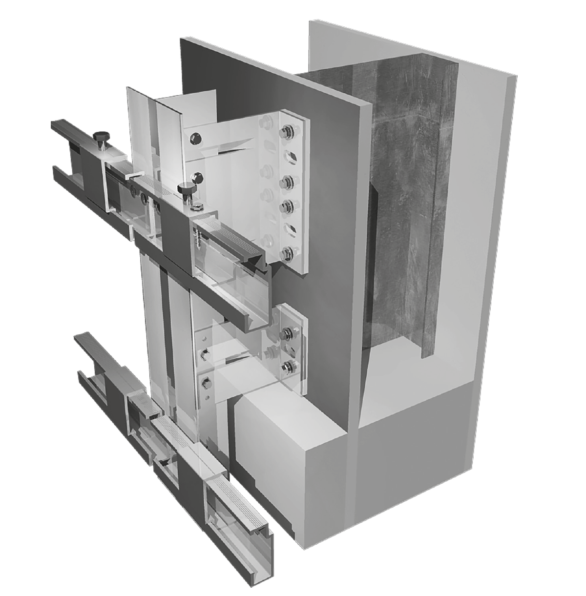
Note: All illustrations are representations of the system and structural design analysis must be sought on a project basis.
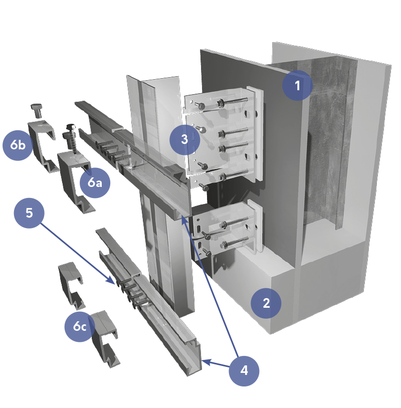
COMPONENTS
 Primary Structure (Concrete, Masonry, SFS or timber)
 Insulation
 DCSO31 HELPING HAND System (Refer to relevant technical guide)
 DCS004 horizontal Carrier Rail
 LT3-5.5X25MM Low profile TEK Screws (2no. per intersection)
 DCS004 Panel Hangers
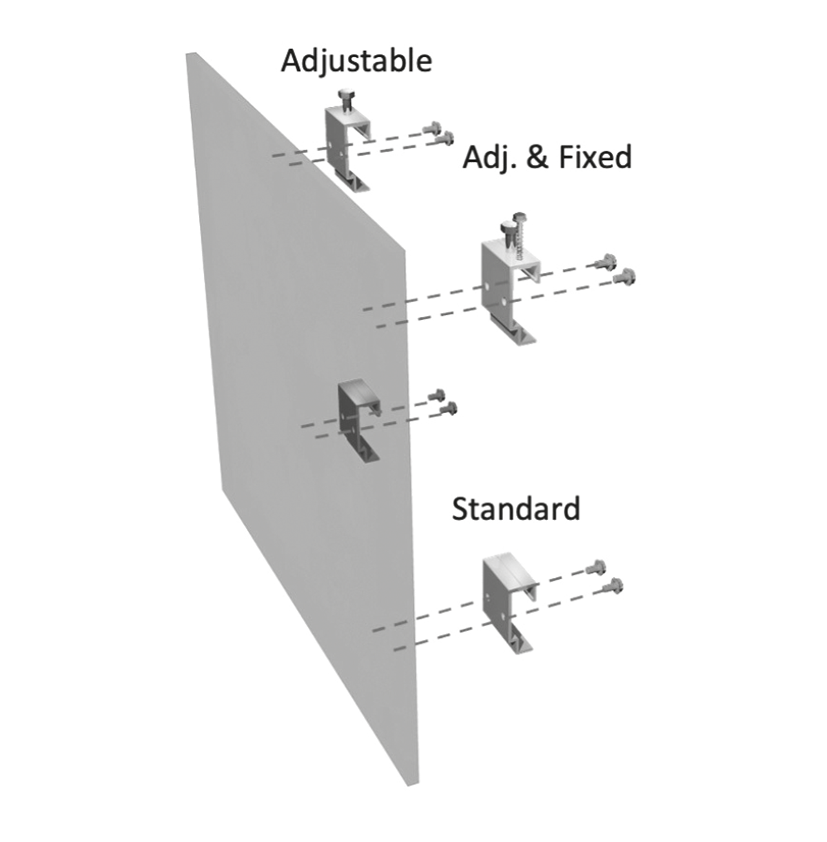
a. Adjustable/Fix Panel Hanger
b. Adjustable Panel Hanger
c. Standard Panel Hanger
Cavity Range
An increase of 26mm would need to be added to framing support system cavity to allow for Downer DCS004 Panel Hangers and Horizontal Carrier Rail.
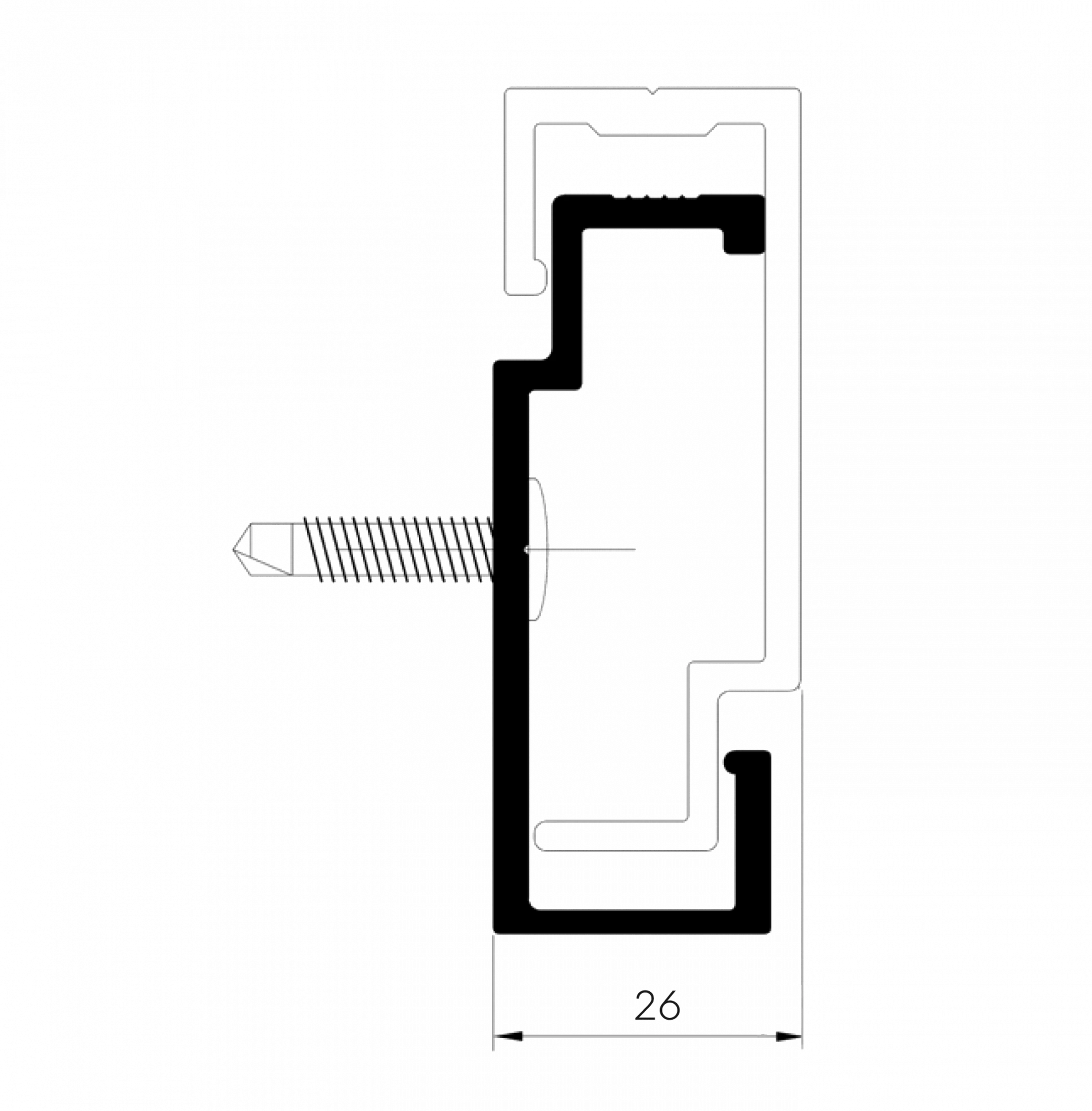
DCS004 Horizontal Carrier Rail
and Hangers
Extruded Alloy Grade 6005A T6
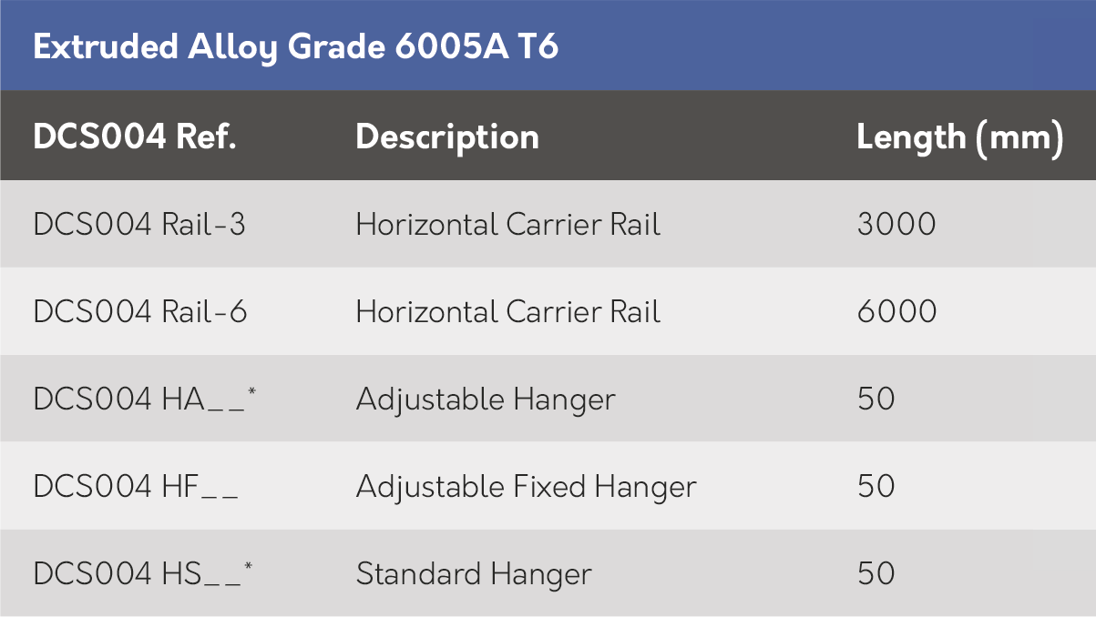
* The last 3 or 4 digits refer to the hanger configuration, see below.
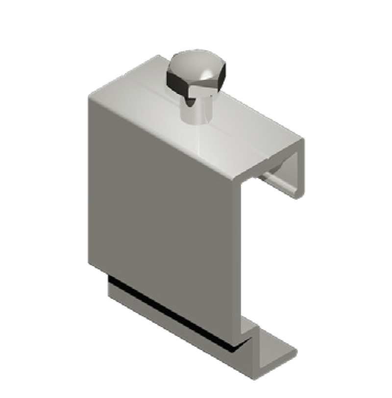
DSCS004HA
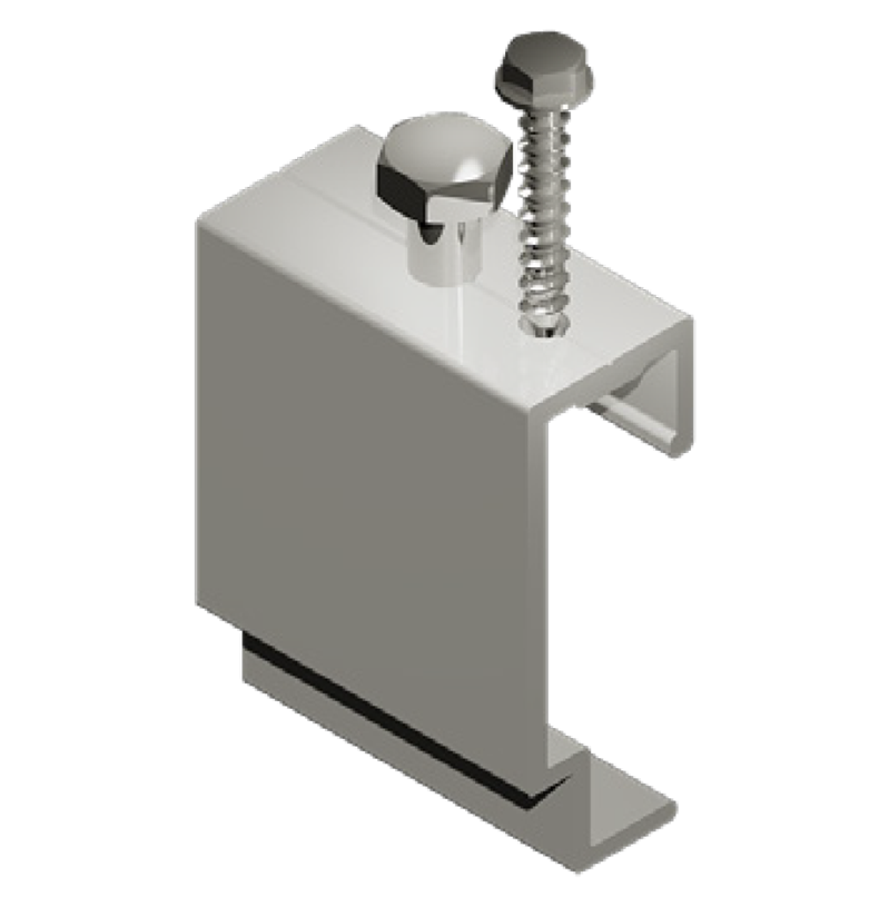
DSCS004HF
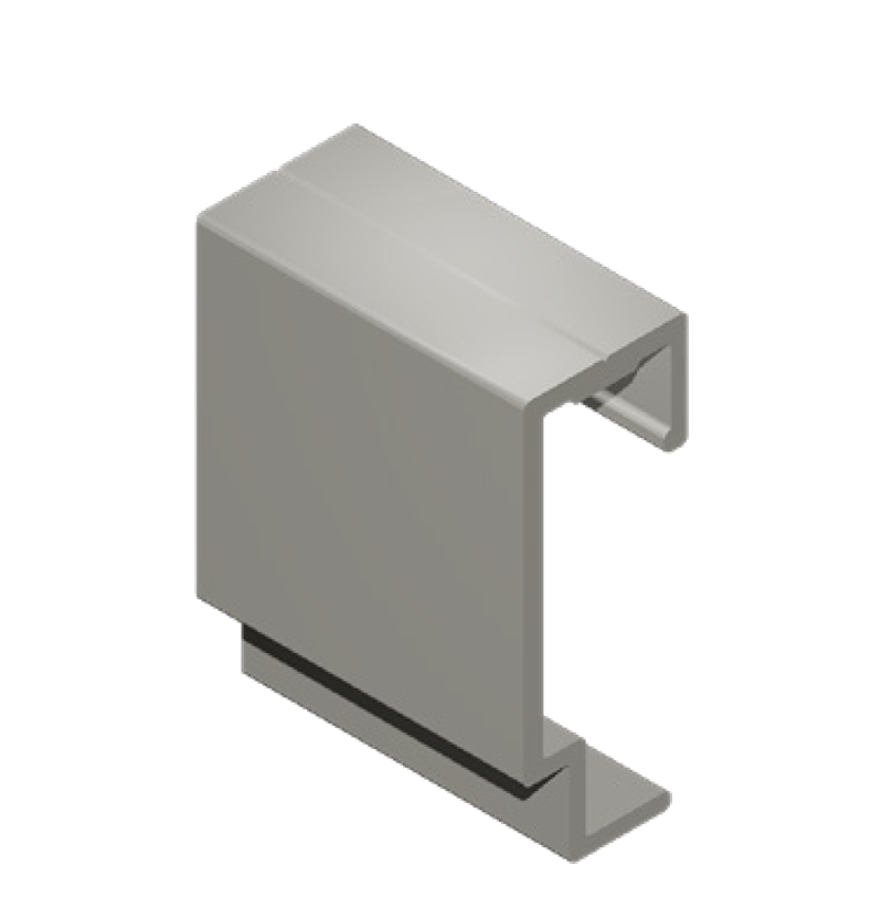
DSCS004HS
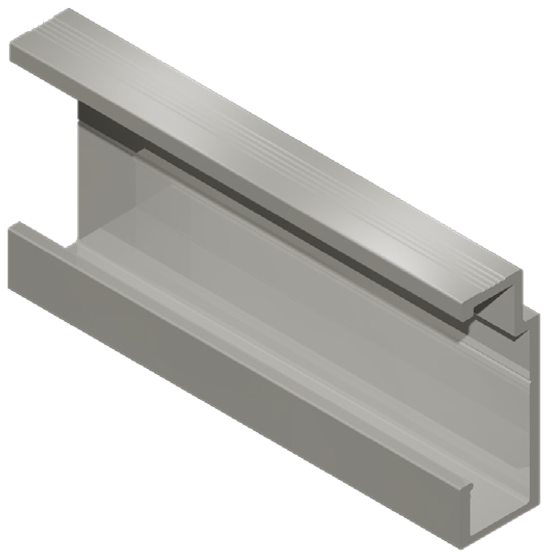
DSCS004 Rail- 3/6
DCS004 Horizontal Carrier Rail and Hangers
• 50A – 2xØ7mm holes @ 30mm
• KE50 – Square Hole 10.2mm (Eternit Keil Anchor)
• K50 – Hex Hole 9.2mm (Keil Anchor)
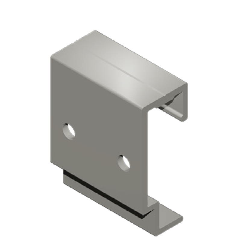
DCS004HS50A
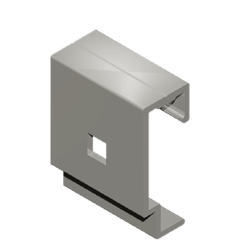
DCS004HSKE50
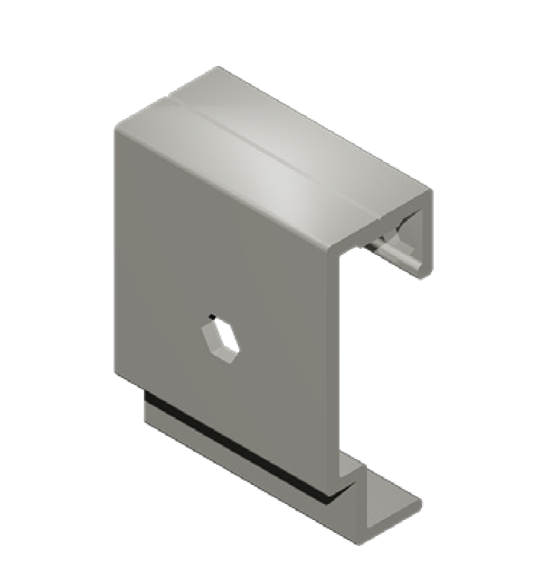
DCS004HSK50
Please contact Downer Framing for any other project specific configurations.
Design Considerations
The ends of any DCS004 Horizontal Carrier Rail unsupported cantilever should be ≤150mm or as dictated by project specific static calculations.
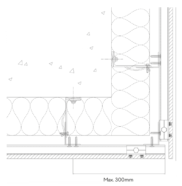
At building corner locations, HCR cantilever can be increased up to max. 300mm and must be strapped to adjacent HCR using an “L” rail angle such as DCS031 60×40 L rail.
DCS004 HCR must not span across and be fixed to the other side of a building movement joint.
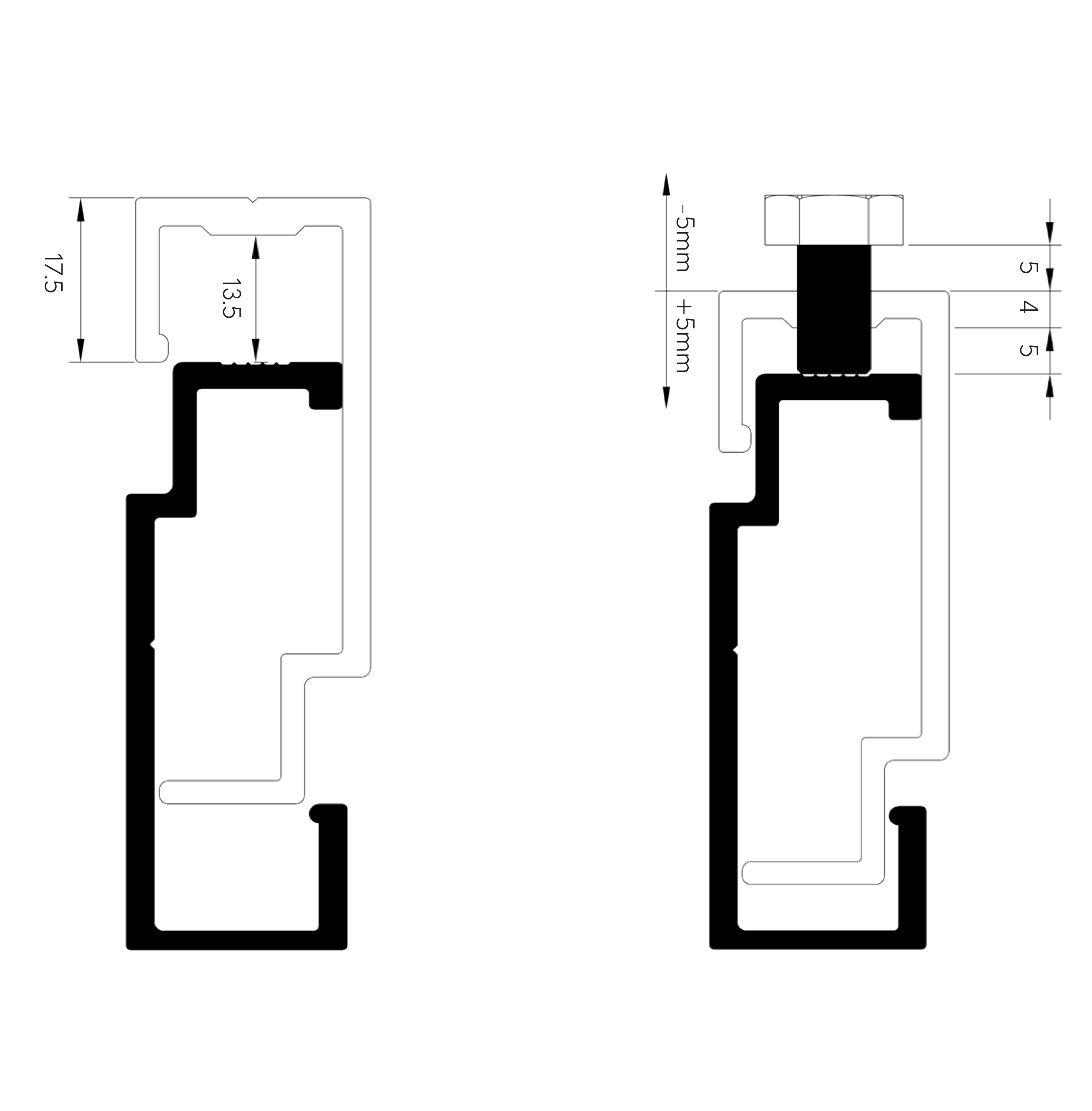
Adjustable panel hangers allow for a 10mm adjustment. A lift of 17.5mm will allow the panel hanger to clear the horizontal rail. Therefore, we advise a minimum of 25mm clearance gap for ease of installation.
A minimum vertical distance of 91mm from fixings between vertically spaced brackets is required for installation of the panel.
If adjustable bolt raises the panel over the allowable limit, remove panel and adjust HCR to suit.
Approvals
Downer DCS004 system has been BBA approved under certificate no. 20/5792.

HORIZONTAL RAILS INSTALLATION
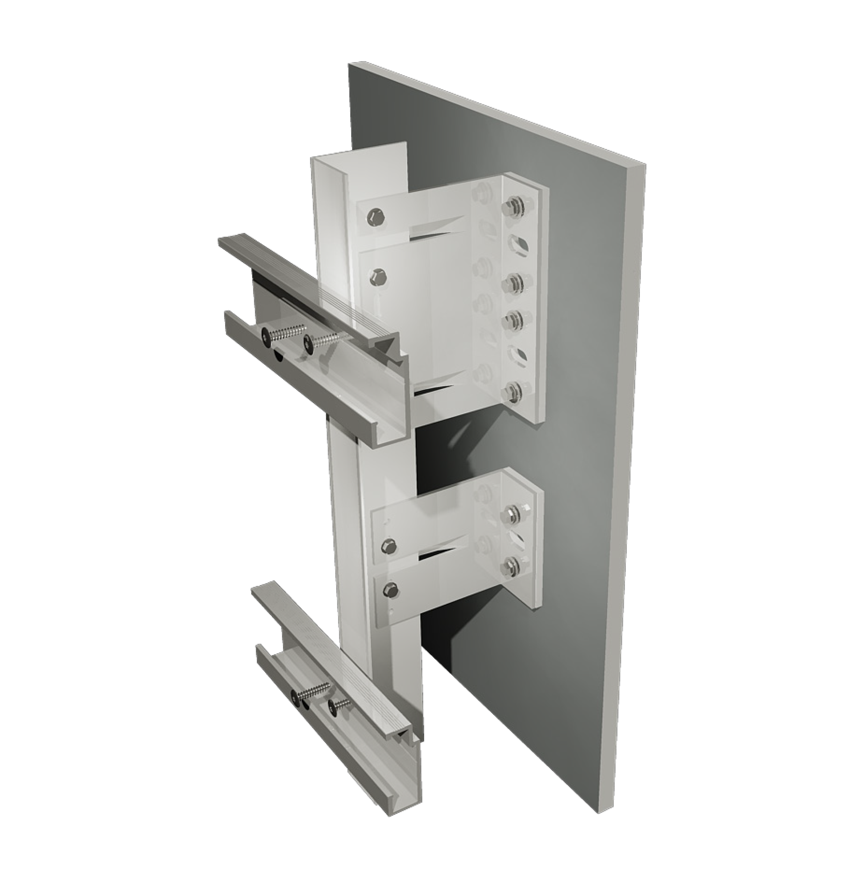
The horizontal cladding rails are fixed onto the vertical sub-frame and should align with DCS004 Hangers fitted to the rear face of the panel.
DCS004 Horizontal Carrier Rails (HCR) are supplied in 3.0 and/or 6.0m lengths. Generally, these are installed in max. 3m lengths and cut to suit project specific detailing (fire barriers, building movement joints, etc).
Layout position of the HCR by projecting horizontal datum lines across the elevation and mark position on to the vertical rails.
Secure the cladding rails to the vertical substructure with 2no. low profile self-drilling 5.5 x 25mm screws per intersection or as dictated by structural calculations.
a. Fixing HCR to L rail (intermediate / end of rails) – all double fix point
b. Fixing HCR ends to T rail (HCR joint) – all double sliding points drilling Ø10mm holes in HCR only.
Each HCR must be level and parallel to the others. Any joints between adjacent rails should be set at a minimum of 10mm for expansion.
Refer to the project design drawings for horizontal cladding rail spacing and position in relation to the approved rainscreen panel layout drawings. The location of the cladding rails and panel hangers is subject to the structural loading, type and weight of the panel and the system application.
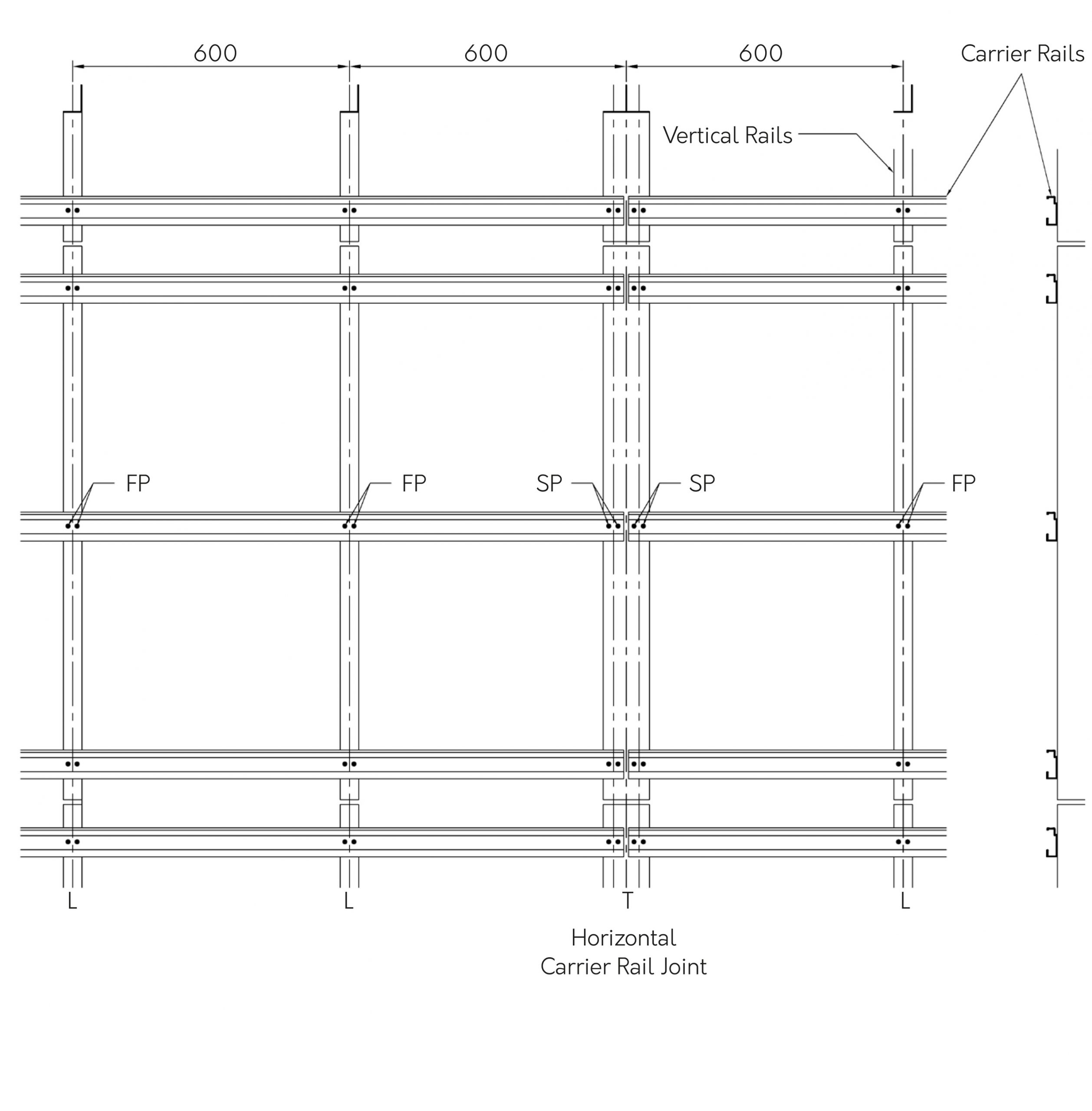
Guideline DCS004 HCR Set out
• FP- Fixed point
• SP – Sliding Point
PANEL HANGER INSTALLATION
Cladding panels are usually supplied flat packed from the factory, fully fabricated and ready for the attachment of the panel hanger brackets and required fixings.
Layout each panel in turn and select the correct hanger type for the corresponding location on the panel, following panel manufacturer’s recommendations.
Generally, the top row consists of adjustable panel hangers to level and adjust the height of the panel with one fixed/adjustable hanger to lock the panel in place closer to the centre. All others to be standard panel hangers.
Attach each panel hanger using recommended board anchor/fixing and torque load following manufacturer’s instructions.
CLADDING PANEL INSTALLATION (General)
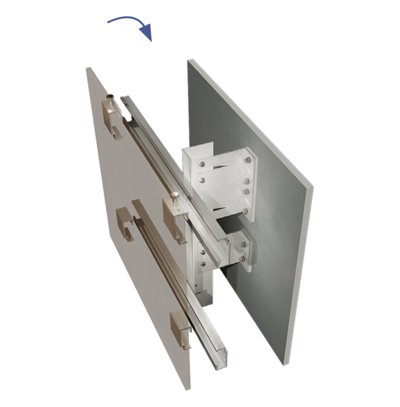
DCS004 Mechanical Secret Fix is a hook-on system with fine level adjustment required to the top row of panel hangers and as such is required to be installed in sequence standard left to right from ground floor upwards.
Before proceeding with panel installation, check horizontal carrier rail set out in relation to panel hanger positions.
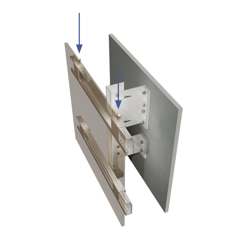
Lift the panel up into place so each panel hanger is hooked onto the horizontal carrier rail.
Position the panel in its final location and using a suitable ratchet spanner adjust the M8 x 14mm hexagonal machine screw located in the top of the adjustable hanger and the adjustable/fixed hanger.
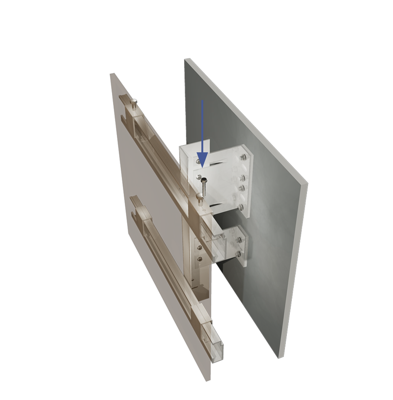
Once the panel is levelled and recommended joint width is set, insert a TEK Screw 5.5 x 35 mm into the pilot hole in the top of the adjustable/fixed hanger. This will lock the panels onto the Horizontal Cladding Rail and prevent them from moving horizontally along the rails.
Delivery and Packaging
Most deliveries are made by standard courier unless specific vehicles are requested (For 6m lengths a rigid sided or larger lorry may be required). All products leaving our factory are packed in a manner to ensure safe delivery to site.
This entails protection by shrink-wrapping and strapping, and with delivery on suitably sized pallets, frames, crates, bundles, or boxes. These normally contain a maximum of 1200kg for pallets and 35kg for non-palletized items for safe handling on site. It should be noted that it is the customer’s responsibility to ensure safe unloading of delivery vehicles.
Pallets are made suitable for forklift off-load only as standard. If pallets are required for craning off-load, maximum loading and size must be advised at the time of ordering.
Site Handling
Components must be handled with care in order to not cause loss or damage. Should it be necessary to store the material on site for any length of time, it should be protected from the elements and the environment. A suitable storage area will need to be set aside, storage should be as near as practicable to the areas of working in order to minimise handling, damage and waste.
Maintenance Instructions
Aluminium profiles and façade accessories subjected to normal circumstances and proper cleaning and maintenance, are guaranteed a long-life span in excess of 35 years.
Contamination by concrete, mortar, cement and such, is extremely harmful and needs to be rinsed immediately with pure water.
CONTACT US
Please contact using the details below or by using the form opposite.
Downer Framing
5 Wainwright Close
Churchfields Industrial Estate
Saint Leonards-on-Sea
East Sussex
TN38 9PP
Tel: +44(0)1424 852 641
Email: info@downerframing.com

