

DCS041
Floor Spanning
DCS041 SYSTEM OVERVIEW
Downer DCS041 floor to floor framing system is designed to provide vertical support to most rainscreen cladding panels using the principle of a ventilated façade with the ability to span over non-load bearing walls and be fixed back to floor slabs.
Wall brackets combined with extruded aluminium box and “T” box profiles provide the installer with an adjustable system allowing for thermal and structural movement and variation in cavity depth to suit project specific requirements.
DCS041 vertical rails offer direct support to the cladding panels by face or adhesive fixing them. It can also be used as a support to other framing systems such us our DCS004 Mechanical Secret Fix or DCS021 Omega and Zeds for horizontal support.


Note: All illustrations are representations of the system and structural design analysis must be sought on a project basis.
COMPONENTS
 Primary Structure (Concrete, Masonry, SFS or timber)
 Insulation
 DCS041 Isolator Pad
Primary Fixing ( varies dependent on Primary Structure)
 DCS041 Wall Bracket
 HBS 100×75 A2 S/S Bolt Set
 DCS041 Box Rail (box or “T” box available as 6m lengths)
 200mm Rail Connecting Spigot
 FDS 65530 W16 Spigot Retaining Screw
DCS041 Wall Brackets / Cavity Range
DCS041 wall brackets are available as standard with 30xØ13mm slots (central or side located) to suit most masonry / concrete anchors and in different sizes ranging from 83 to 153mm projection

DCS041 – WALL BRACKET CENTRE FIXING

DCS041 – WALL BRACKET SIDE FIXING
Framing Zone - Range (R)

Add 5mm to include – Thermal Isolator Pad


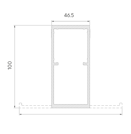
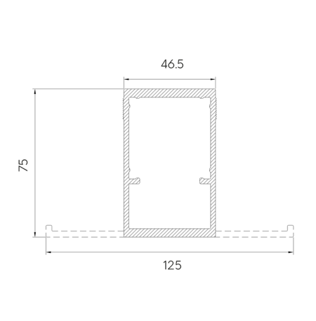
DCS041 Rails

![]()
SITE CHECKLIST
Before commencing installation of DCS041 framing system please make sure you have received the following information:
- Project specific static calculations from your Downer Designer portal. Or get in touch with the team direct –info@downerdesigner.com. These will dictate maximum vfloor span, location of fixed and sliding point brackets and size / type of primary fixing based on project specific dynamic and dead loads.
- DCS041 Wall brackets and rails set out drawings* showing location of dead load (fix point), wind restraint / expansion brackets (sliding point) and box rails horizontal spacing and joints.
Get project specific stats direct via Downer Designer – your dedicated portal.

Just provide us with your project info and we’ll prepare your optimised project pack.
DCS041 WALL BRACKETS
SUBSTRATES
DCS041 wall brackets are available with either 1no. (83 & 118) or 2no. (153) 30xØ13mm slots to suit primary anchors specified by project specific static calculations and/or on-site pull out tests.
Concrete or masonry substrates
Please contact Downer Technical for any other substrates.

FIX & SLIDING POINTS
All our brackets are available with both Ø5.1mm holes and 15xØ5.5mm slots.
Fix point (Absorbs dead load)
Vertical rail secured using HBS 10X75mm bolt set through Ø11mm hole.

Sliding point (Absorbs live loads and rail expansion)
Vertical rail secured using HBS 10X75mm bolt set through 28xØ11mm slot.

Please refer to project specific static calculations for correct location of fix & sliding point brackets and quantity of each.
Typical Rail Set Out

![]()
Design Considerations
Vertical rails and DCS041 wall brackets should be set out in accordance with the structural engineers’ calculations or necessary building regulation T box sections generally provide vertical support at panel joint and box rail sections provide vertical support for intermediate fixing and corner/reveal support.
T box and box rails are generally supplied in 6.0metre lengths.
Rainscreen cladding fixings should be positioned close to the centre line of the front face of the box rail / legs of T box.
There must be a minimum 15mm gap between the ends of adjacent rails to allow for expansion and cladding panels should never be fixed to two adjacent rails across the expansion gap.
Do not secure the upper and lower rails using the same wall bracket.
DCS041 Helping Hand bracket Isolator pads must be used when there is risk of bimetallic corrosion or thermal bridging and to isolate the bracket from cementitious surfaces. For ease of lining and levelling rails start from a predetermined datum line corner/opening or return.
The DCS041 system is designed to span between structural floor slabs, so all the supporting wall brackets are fitted to slab edges.
Approvals
Downer DCS041 system has been BBA approved under certificate no. 20/5792.

![]()
INSTALLATION PROCEDURE
![]() Mark-up location of DCS041 wall brackets ensuring that fixed and sliding points wall brackets are positioned correctly.
Mark-up location of DCS041 wall brackets ensuring that fixed and sliding points wall brackets are positioned correctly.
![]() Install DCS041 wall brackets with isolator pads positioned between the rear of the brackets and the building substrate. Use the appropriate primary anchors as dictated by project specific static calculations.
Install DCS041 wall brackets with isolator pads positioned between the rear of the brackets and the building substrate. Use the appropriate primary anchors as dictated by project specific static calculations.
![]() If mineral wool insulation is to be fitted ensure that once this is in place access is available to attach the T box and Box rails to the wall brackets.
If mineral wool insulation is to be fitted ensure that once this is in place access is available to attach the T box and Box rails to the wall brackets.
![]() Insert vertical box rails into the DCS041 wall brackets, adjust, check line and level and secure each rail by drilling an 11mm diameter hole through the fix point hole or sliding point slot.
Insert vertical box rails into the DCS041 wall brackets, adjust, check line and level and secure each rail by drilling an 11mm diameter hole through the fix point hole or sliding point slot.
![]() Vertical box rails should always engage a minimum of 30mm into the wall bracket.
Vertical box rails should always engage a minimum of 30mm into the wall bracket.
![]() Fit the M10 x 75mm SS rail bolt/washers/locknuts to each hole, torque load and secure.
Fit the M10 x 75mm SS rail bolt/washers/locknuts to each hole, torque load and secure.


![]() Each T Box/Box Rail is jointed at the slab edges by inserting a 200mm long connecting spigot into the rear chamber of each rail. Then, fix a 2no FDS65530 W 16 x 30mm TEK screw approx. 30mm above the joint and 30mm spaced, centrally to the box spigot.
Each T Box/Box Rail is jointed at the slab edges by inserting a 200mm long connecting spigot into the rear chamber of each rail. Then, fix a 2no FDS65530 W 16 x 30mm TEK screw approx. 30mm above the joint and 30mm spaced, centrally to the box spigot.

![]() Continue installation of rails following the same procedure as above to complete the sub grid.
Continue installation of rails following the same procedure as above to complete the sub grid.
![]() Proceed with the installation of the remainder of the rainscreen system.
Proceed with the installation of the remainder of the rainscreen system.
![]() When completed and before commencing cladding panel installation, final checks should be carried out on:
When completed and before commencing cladding panel installation, final checks should be carried out on:
a. Level and plumb of vertical rail.
b. Correct location of fix and sliding point wall brackets and spigot.
c. Correct torque load applied to primary anchors as recommended by fixing manufacturer.
![]() Proceed with cladding panel installation following cladding manufacturer guidelines.
Proceed with cladding panel installation following cladding manufacturer guidelines.
![]()
Delivery and Packaging
Most deliveries are made by standard courier unless specific vehicles are requested (For 6m lengths a rigid sided or larger lorry may be required). All products leaving our factory are packed in a manner to ensure safe delivery to site.
This entails protection by shrink-wrapping and strapping, and with delivery on suitably sized pallets, frames, crates, bundles, or boxes. These normally contain a maximum of 1200kg for pallets and 35kg for non-palletized items for safe handling on site. It should be noted that it is the customer’s responsibility to ensure safe unloading of delivery vehicles.
![]() Pallets are made suitable for forklift off-load only as standard. If pallets are required for craning off-load, maximum loading and size must be advised at the time of ordering.
Pallets are made suitable for forklift off-load only as standard. If pallets are required for craning off-load, maximum loading and size must be advised at the time of ordering.
![]()
Site Handling
Components must be handled with care in order to not cause loss or damage. Should it be necessary to store the material on site for any length of time, it should be protected from the elements and the environment. A suitable storage area will need to be set aside, storage should be as near as practicable to the areas of working in order to minimise handling, damage and waste.
![]()
Maintenance Instructions
Aluminium profiles and façade accessories subjected to normal circumstances and proper cleaning and maintenance, are guaranteed a long-life span in excess of 35 years as stated in Downer BBA certificate 20/5792
Contamination by concrete, mortar, cement and such, is extremely harmful and needs to be rinsed immediately with pure water.
CONTACT US
Please contact using the details below or by using the form opposite.
Downer Framing
5 Wainwright Close
Churchfields Industrial Estate
Saint Leonards-on-Sea
East Sussex
TN38 9PP
Tel: +44(0)1424 852 641
Email: info@downerframing.com
